Getting Started with CH32V003: Difference between revisions
Jump to navigation
Jump to search
| Line 46: | Line 46: | ||
'''Other websites for the CH32V003:''' | '''Other websites for the CH32V003:''' | ||
https://www.cnx-software.com/2023/02/22/ch32v003-risc-v-mcu-gets-1-5-development-board-open-source-gcc-toolchain-and-flasher-utility/ | https://www.cnx-software.com/2023/02/22/ch32v003-risc-v-mcu-gets-1-5-development-board-open-source-gcc-toolchain-and-flasher-utility/ | ||
https://hackaday.com/2023/03/02/a-ch32v003-toolchain-if-you-can-get-one-to-try-it-on/ | |||
https://github.com/AlexanderMandera/arduino-wch32v003 | |||
https://www.tindie.com/products/adz1122/ch32v003-risc-v-mcu-development-board/ | |||
I'm trying to find a port of FreeRTOS for CH32V003 - Links: | |||
https://www.freertos.org/Using-FreeRTOS-on-RISC-V.html | |||
==Current Project Status== | ==Current Project Status== | ||
Revision as of 11:10, 16 April 2023
After watching David Jones's YouTube "EEVblog 1524 - The 10 CENT RISC V Processor! CH32V003",
https://www.youtube.com/watch?v=L9Wrv7nW-S8&ab_channel=EEVblog
I had to learn more about this chip.
Where to get a CH32V003 development board
I ordered this board: along with the programmer and cable for $7.50:
https://www.aliexpress.us/item/3256805035436953.html

Repository for board with documentation and example code: https://github.com/wuxx/nanoCH32V003
The github repo's README.md file: https://github.com/wuxx/nanoCH32V003#readme
                  Schematic: https://github.com/wuxx/nanoCH32V003/blob/master/hardware/nanoCH32V003.pdf

I created a RISC-V folder under Documents like so:
C:\Users\Jim\Documents\RISC-V

While inside the RISC-V folder, I cloned the repository like so:
 git clone https://github.com/wuxx/nanoCH32V003.git

Inside the "doc" folder is the zipfile, CH32V003EVT.ZIP, with "EVT" folder inside.
Unzip the EVT folder into "doc", so you have the example code available.

CH32V003 website: http://www.wch-ic.com/products/CH32V003.html
The device on the development board is: CH32V003F4U6, with 18 GPIOs in a QFN20 package
MounRiver Studio IDE
Download the latest version of MounRiver Studio IDE from the official website:
http://www.mounriver.com/  and install it.
More info concerning the board
According to the schematic, the LED is connected to PD6
WCH-LinkE v1.0
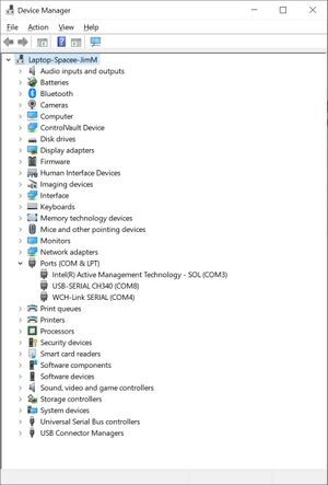
After plugging in the WCH-Link USB-Serial programmer, the device should display in Window Device Manager

The programmer comes with a 4-conductor cable, wire colors: brown (1), red (2), orange (3), yellow (4)
WCH-Link Utility
This software tool connects with the WCH-LinkE programmer, and allows the user to read, write, examine
program data written to the RISC-V device.
https://www.wch.cn/downloads/WCH-LinkUtility_ZIP.html
Notes & References
As noted in the YouTube EEVblog, the TSSOP20 package for this part appears to be pin
compatible with the STM8S003F3, https://www.st.com/resource/en/datasheet/stm8s003f3.pdf, at 1/3rd the price.
The UFQFPN20 package doesn't appear to be pin compatible.
Other websites for the CH32V003:
https://www.cnx-software.com/2023/02/22/ch32v003-risc-v-mcu-gets-1-5-development-board-open-source-gcc-toolchain-and-flasher-utility/
https://hackaday.com/2023/03/02/a-ch32v003-toolchain-if-you-can-get-one-to-try-it-on/
https://github.com/AlexanderMandera/arduino-wch32v003
https://www.tindie.com/products/adz1122/ch32v003-risc-v-mcu-development-board/

I'm trying to find a port of FreeRTOS for CH32V003 - Links:
https://www.freertos.org/Using-FreeRTOS-on-RISC-V.html
Current Project Status
Today, 4/15/23, I started to work with this nanoCH32V003 development board.
I soldered header pins to the development board.  I then connected GND, DIO, and 3V3 signals
from the 3-wire programmer interface to the WCH-LinkE board.
My Wiring
Target         LinkE
GND  - brown  - GND
DIO  - yellow - SWDIO
3V3  -  red   - 3V3

When I attempted to use the WCH-Link Utility with the WCH-LinkE, the tool indicated
I needed to update the firmware.  After a few attempts, this process completed successfully.
Now, using WCH-Link Utility, I'm able to read the flash program from the target and save it to a file.  (Good first step)
I built the sample GPIO project, "GPIO_Toggle", downloaded the resulting GPIO_Toggle.bin file to the target board.
NOTHING!  No Blinky!
I'm able to reprogram the board using the saved flash data.  - That works!  LED: 500ms high, 500ms low.

With a scope in hand, I see PD0 is toggling nicely.
Seems the example software was developed for a different board or something.
Changed the software to use PD6, that connects to the on-board LED.  The LED is now blinking as expected!

The GPIO example, GPIO_Toggle project, also enables serial debug output on D6 (UTX).
After attaching an FTDI USB-Serial board to GND and D6, I'm receiving serial debug on my Tera Term terminal.
{{#if:|{{#ifexpr:({{#time:U|{{{3}}}}} - {{#time:U|now}}) > 0|SystemClk:48000000|SystemClk:48000000}}|SystemClk:48000000}}
{{#if:|{{#ifexpr:({{#time:U|{{{3}}}}} - {{#time:U|now}}) > 0|GPIO Toggle TEST|GPIO Toggle TEST}}|GPIO Toggle TEST}}