NUCLEO-C031C6: Difference between revisions
Jump to navigation
Jump to search
No edit summary |
No edit summary |
||
| Line 51: | Line 51: | ||
==References== | ==References== | ||
[https://developer.arm.com/Processors/Cortex-M0-Plus:Arm M0+ Core] | [https://developer.arm.com/Processors/Cortex-M0-Plus:Arm M0+ Core] | ||
https://developer.arm.com/Processors/Cortex-M0-Plus | |||
Revision as of 22:31, 19 February 2023
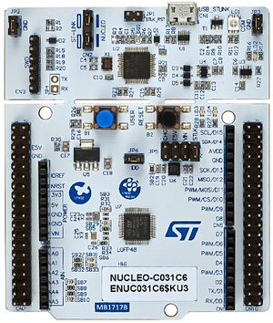
The NUCLEO-C031C6 development board uses the STM32-C036C6 as the target processor. This processor was developed for cost sensitive applications in an attempt to gain more market share from the 8-bit processor world.
STMicro derived this part from the STM32-G0 family.
At first glance, I thought, "This isn't a 64-pin device." I was right. That's a 48-pin part (their largest C0 family part)

Processor: STM32-C031C6
Arm® Cortex®-M0+ core
32KB Flash
12KB SRAM
48MHz SYSCLK
32.768 kHz crystal oscillator
Internal 48MHz RC oscillator
This part has the following peripherals:
2 USARTs
5 timers: TIM1, TIM3, TIM14, TIM16, TIM17, all 16-bit, all PWM capable
1 SPI / I2S interface
1 I2C
1 ADC (multiple channel)
CRC calculation unit
IWDG independent watchdog
WWDG system window watchdog
Unique 96-bit signature
Board Hardware
* Green LED, LD4, connected to PA5, illuminates when driven high, isolated by a transistor to not impact current measurements
* Blue PushButton, B1, connects to PC13, grounding the signal when pressed
* Reset Button, B2, connects to NRST, used to reset the STM32 microcontroller
* 32,768Hz crystal oscillator, LSE, used for Real Time Clock (RTC), connected to PC14-OSC32_IN and PC15-OSC32_OUT
* 8MHz MC0, is provided by the 8MHz crystal oscillator from the attached ST-Link, into PF0-OSC_IN
* UART1 connects the target processor to the ST-Link, providing a USB COM port connection on the host computer. Uses PB6 for TX, and PB7 for RX.
* UART2 connects the target processor to the ST-Link, providing a USB COM port connection on the host computer. Uses PA2 for TX, and PA3 for RX.
* I2C1 connects to the Arduino Headers (SCL/D15, SDA/D14) using PB8(SCL) and PB9(SDA)
* ST-Link connects to TCK (PA14), TMS (PA13)
https://www.st.com/en/evaluation-tools/nucleo-c031c6.html
It's interesting to note, that by default, UART1 is configures for the board, but not UART2. This is different then most of the NUCLEOs.
Where is everything?
Once an STM32 processor or development board is selected, STM32CubeIDE downloads and installs
a firmware package for the device selected.
I found the install location for the “C0” firmware here:
C:\Users\JimMerkle\STM32Cube\Repository\STM32Cube_FW_C0_V1.0.1
Within this folder are header files, HAL source code, middleware, driver code,
example code, and documentation for the firmware package.
Each project includes a copy of the header files needed for a build.
(Just drill down inside the project's Driver folder.)  Example:
C:\Users\JimMerkle\Documents\STM32_Projects\NUCLEO-C031C6_Blinky\Drivers\STM32C0xx_HAL_Driver\Inc\stm32c0xx_hal_gpio.h
References
M0+ Core
https://developer.arm.com/Processors/Cortex-M0-Plus