Getting Started with CH32V003: Difference between revisions
Jump to navigation
Jump to search
No edit summary |
No edit summary |
||
| Line 86: | Line 86: | ||
'''SystemClk:48000000''' | '''SystemClk:48000000''' | ||
'''GPIO Toggle TEST''' | '''GPIO Toggle TEST''' | ||
==Other CH32V003 Projects== | |||
Currently storing my CH32V003 projects on github: | |||
1us Timer : https://github.com/JimMerkle/CH32V003_Timer_1us | |||
command_line: https://github.com/JimMerkle/CH32V003_command_line | |||
Revision as of 12:28, 16 August 2024
After watching David Jones's YouTube "EEVblog 1524 - The 10 CENT RISC V Processor! CH32V003",
https://www.youtube.com/watch?v=L9Wrv7nW-S8&ab_channel=EEVblog
I had to learn more about this chip.
Where to get a CH32V003 development board
I ordered this board: along with the programmer and cable for $7.50:
https://www.aliexpress.us/item/3256805035436953.html

Repository for board with documentation and example code: https://github.com/wuxx/nanoCH32V003
The github repo's README.md file: https://github.com/wuxx/nanoCH32V003#readme
                  Schematic: https://github.com/wuxx/nanoCH32V003/blob/master/hardware/nanoCH32V003.pdf

I created a RISC-V folder under Documents like so:
C:\Users\Jim\Documents\RISC-V

While inside the RISC-V folder, I cloned the repository like so:
 git clone https://github.com/wuxx/nanoCH32V003.git

Inside the "doc" folder is the zipfile, CH32V003EVT.ZIP, with "EVT" folder inside.
Unzip the EVT folder into "doc", so you have the example code available.
This zip file was provided by WCH, providing examples for the CH32V003,
not specifically for the nanoCH32V003 board.

CH32V003 website: http://www.wch-ic.com/products/CH32V003.html
The device on the development board is: CH32V003F4U6, with 18 GPIOs in a QFN20 package
MounRiver Studio IDE
Download the latest version of MounRiver Studio IDE from the official website:
http://www.mounriver.com/  and install it.
More info concerning the board
According to the schematic, the LED is connected to PD6
If using the GPIO example project, need to change source code to use PD6, not PD0.
WCH-LinkE v1.0
After plugging in the WCH-Link USB-Serial programmer, the device should display in Window Device Manager

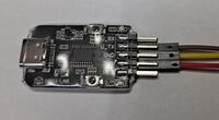
The programmer comes with a 4-conductor cable, wire colors: brown (1), red (2), orange (3), yellow (4)
I connected the LinkE programmer to the nanoCH32V003 target board as follows:
Target         LinkE
GND  - brown  - GND
DIO  - yellow - SWDIO
3V3  -  red   - 3V3


WCH-Link Utility
This software tool connects with the WCH-LinkE programmer, and allows the user to read, write, examine
program data written to the RISC-V device.
https://www.wch.cn/downloads/WCH-LinkUtility_ZIP.html
Notes & References
As noted in the YouTube EEVblog, the TSSOP20 package for this part appears to be pin
compatible with the STM8S003F3, https://www.st.com/resource/en/datasheet/stm8s003f3.pdf, at 1/3rd the price.
The UFQFPN20 package doesn't appear to be pin compatible.
Other websites for the CH32V003:
https://www.cnx-software.com/2023/02/22/ch32v003-risc-v-mcu-gets-1-5-development-board-open-source-gcc-toolchain-and-flasher-utility/
https://hackaday.com/2023/03/02/a-ch32v003-toolchain-if-you-can-get-one-to-try-it-on/
https://github.com/AlexanderMandera/arduino-wch32v003
https://www.tindie.com/products/adz1122/ch32v003-risc-v-mcu-development-board/
Example code provided by the processor manufacturer: http://www.wch.cn/downloads/CH32V003EVT_ZIP.html
https://www.wch.cn/downloads/file/409.html

I2C Example using AT24C256 EEPROM - Link:
https://pallavaggarwal.in/2023/10/05/ch32v003-programming-i2c-eeprom/
Current Project Status
Today, 4/15/23, I started to work with this nanoCH32V003 development board.
I soldered on the header pins.  I then connected GND, DIO, and 3V3 signals
from the 3-wire programmer interface to the WCH-LinkE board.

When I attempted to use the WCH-Link Utility with the WCH-LinkE, the tool indicated
I needed to update the firmware.  After a few attempts, this process completed successfully.
Now, using WCH-Link Utility, I'm able to read the flash program from the target and save it to a file.  (Good first step)
I built the sample GPIO project, "GPIO_Toggle", downloaded the resulting GPIO_Toggle.bin file to the target board.
NOTHING!  No Blinky!
I'm able to reprogram the board using the saved flash data.  - That works!  LED: 500ms high, 500ms low.

With a scope in hand, I see PD0 is toggling nicely.
Seems the example software was developed for a different board or something.
Changed the software to use PD6, that connects to the on-board LED.  The LED is now blinking as expected!

The GPIO example, GPIO_Toggle project, also enables serial debug output on D6 (UTX).
After attaching an FTDI USB-Serial board to GND and D6, I'm receiving serial debug on my Tera Term terminal.
SystemClk:48000000
GPIO Toggle TEST
Other CH32V003 Projects
Currently storing my CH32V003 projects on github:
1us Timer : https://github.com/JimMerkle/CH32V003_Timer_1us
command_line: https://github.com/JimMerkle/CH32V003_command_line