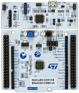
NUCLEO-C031C6
The NUCLEO-C031C6 development board uses the STM32-C036C6 as the target processor. This processor was developed for cost sensitive applications in an attempt to gain more market share from the 8-bit processor world.
STMicro derived this part from the STM32-G0 family.
At first glance, I thought, "This isn't a 64-pin device." I was right. That's a 48-pin part (their largest C0 family part)

Processor: STM32-C031C6
Arm® Cortex®-M0+ core
32KB Flash
12KB SRAM
48MHz SYSCLK
32.768 kHz crystal oscillator
Internal 48MHz RC oscillator
Peripherals:
2 USARTs
5 timers: TIM1, TIM3, TIM14, TIM16, TIM17, all 16-bit, all PWM capable
1 SPI / I2S interface
1 I2C
1 ADC (multiple channel)
CRC calculation unit
IWDG independent watchdog
WWDG system window watchdog
Unique 96-bit signature
Nucleo Board
* Green LED, LD4, connected to PA5, illuminates when driven high, isolated by a transistor to not impact current measurements
* Blue PushButton, B1, connects to PC13, grounding the signal when pressed
* Reset Button, B2, connects to NRST, used to reset the STM32 microcontroller
* 32,768Hz crystal oscillator, LSE, used for Real Time Clock (RTC), connected to PC14-OSC32_IN and PC15-OSC32_OUT
* 8MHz MC0, is provided by the 8MHz crystal oscillator from the attached ST-Link, into PF0-OSC_IN
* UART2 connects the target processor to the ST-Link, providing a USB COM port connection on the host computer. Uses PA2 for TX, and PA3 for RX.
* I2C1 connects to the Arduino Headers (SCL/D15, SDA/D14) using PB8(SCL) and PB9(SDA)
* ST-Link connects to TCK (PA14), TMS (PA13)
https://www.st.com/en/evaluation-tools/nucleo-c031c6.html
It was interesting to note, that by default, UART1 was configured for the board, but not UART2. This is different then most of the NUCLEOs.
Fixes
* The default NUCLEO-C031C6 project configures UART1 - Disable this
* Enable UART2 - use this if you want serial printf() support
STMicro Hands-on workshop
https://content.st.com/stm32c0-workshop-ame.html
Agenda
Overview of the STM32C0 series
Hands-on demonstrations
Lab 1 Blinky: Blink an LED by software
Lab 2 PWM: Use hardware (PWM timer) to blink an LED
Lab 3 EXTI: External Interrupt using a push button
Lab 4 Printf: Printf debugging using UART communication
Lab 5 LL Driver: Example using Low Layer Driver
Lab 6 ADC (optional): ADC example using DMA
Where is everything?
Once an STM32 processor or development board is selected, STM32CubeIDE downloads and installs
a firmware package for the device selected.
I found the install location for the “C0” firmware here:
C:\Users\JimMerkle\STM32Cube\Repository\STM32Cube_FW_C0_V1.0.1
Within this folder are header files, HAL source code, middleware, driver code,
example code, and documentation for the firmware package.
Each project includes a copy of the header files needed for a build.
(Just drill down inside the project's Driver folder.)  Example:
C:\Users\JimMerkle\Documents\STM32_Projects\NUCLEO-C031C6_Blinky\Drivers\STM32C0xx_HAL_Driver\Inc\stm32c0xx_hal_gpio.h
References
M0+ Core
https://developer.arm.com/Processors/Cortex-M0-Plus