Getting Started with STM32
Although this getting started class will work well for many of the STM32 processors and boards, we will focus on the NUCLEO-F103RB board with its STM32-F103RB processor.
Class Description
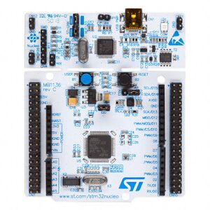
64-Pin NUCLEO Board

* Green LED, LD2, connected to PA5, illuminates when driven high
* Blue PushButton, B1, connects to PC13, grounding the signal when pressed
* 32,768Hz crystal oscillator, LSE, used for Real Time Clock (RTC)
* 8MHz HSE, is provided by the 8MHz crystal oscillator from the attached ST-Link, into PD0
* UART2 connects the target processor to the ST-Link, providing a USB COM port connection on the host computer. Uses PA2 for TX, and PA3 for RX.
* ST-Link connects to TCK (PA14), TMS (PA13)
Board: https://www.st.com/en/evaluation-tools/nucleo-f103rb.html
Manual: https://www.st.com/resource/en/user_manual/um1724-stm32-nucleo64-boards-mb1136-stmicroelectronics.pdf
Schematic: https://www.st.com/resource/en/schematic_pack/nucleo_64pins_sch.zip
Processor: STM32F103RBT6
* 128KB Flash
* 20KB SRAM
* 72MHz clock
* Single-cycle multiplication and hardware division
* 2.0 to 3.6 V application supply and I/Os
* Within this part series, this is considered a "Medium-density device",
  and as such, has the following peripherals:
* 3 USARTs
* 3 16-bit timers
* 2 SPIs, 2 I2Cs, USB, CAN, 1 PWM Timer, 2 ADCs
Notes:
   "Low-density device" has fewer peripherals.
   "High-density device" has more peripherals.
Software - Development Tools - IDE
I recommend creating an STMicro account to make multiple downloads easier.
Download the following tool(s) from STMicro:
https://www.st.com/en/development-tools/stm32cubeide.html  (Required)
Optional tools (not necessary for the class)
https://www.st.com/en/development-tools/stm32-software-development-tools.html
STM32CubeProg - Programming tool to write/read firmware to/from the target processor
STSW-Link007 - ST-Link Firmware Upgrade tool
STSW-Link009 - Windows Device Drivers for ST-Link adapters
Installing STM32CubeIDE_1.10.1
* Allow the software to install at C:/ST/STM32CubeIDE_1.10.1
* When asked where to store project files, I recommend creating a path off of C:/Users/YourName/Documents
   Something like: C:/Users/YourName/Documents/STM32_Projects
   This makes your projects easy to find and backup.
Create a New STM32CubeIDE_1.10.1 Project
1 Click "Start new STM32 project", then select the "Board Selector" tab
2 In the Commercial Part Number box, type "NUCLEO-F103RB", select the board, and then click "Next>" at the bottom
3 Since I have several STM32 boards, I like to have the board name in the name of the project
  I used: "NUCLEO-F103RB_Blinky" as the project name
4 Select "C++" (This allows both C and C++), Executable, STM32Cube Proect Type, Finish
5 Initialize all peripherals with their default Mode ? - Yes
6 Device Configuration Tool editor is associated with Device Configuration Tool perspective.
   Do you want to open this perspective now?  (Select Yes to see what's configured)

7 Under "Project Manager Tab", Linker Settings, I set both Minimum Heap Size and Minimum Stack Size to 0x400 (1K bytes each)
8 On the left, Project Explorer window, Open Core->Src->main.c
Note: If you examine the source code, you will see that the following functions get called:
 * HAL_Init()
 * SystemClockConfig()
 * MX_GPIO_Init()
 Then, the code enters an empty while loop.  Using the JTAG/SWD debugger, we can build, run, and debug the code,
 but it will be rather boring...

9 Find the infinite loop inside the main() function, and add the following two {{#if:|{{#ifexpr:({{#time:U|{{{3}}}}} - {{#time:U|now}}) > 0|highlighted lines of code:|highlighted lines of code:}}|highlighted lines of code:}}

 /* Infinite loop */
 /* USER CODE BEGIN WHILE */
 while (1)
 {
{{#if:|{{#ifexpr:({{#time:U|{{{3}}}}} - {{#time:U|now}}) > 0|   HAL_GPIO_TogglePin(LD2_GPIO_Port,LD2_Pin);
   HAL_Delay(500);|   HAL_GPIO_TogglePin(LD2_GPIO_Port,LD2_Pin);
   HAL_Delay(500);}}|   HAL_GPIO_TogglePin(LD2_GPIO_Port,LD2_Pin);
   HAL_Delay(500);}}
   /* USER CODE END WHILE */

   /* USER CODE BEGIN 3 */
 }

 NOTE:
 Be sure to always place your code between the USER CODE BEGIN and USER CODE END comments
 This will protect your code from being removed should you make changes using the STM32CubeMX again.

10 Click the Hammer Icon for "Build"
   The program will be compiled, linked, and located to run on your NUCLEO-F103RB
11 Click the Right Pointing Green Arrow Icon for "Run"
  The program will be downloaded to the device and begin execution.
  You should see LED2 blinking at this point.
Miscellaneous
Fix Eclipse's Small Icon issue
1 Find the installation folder for your STM32CubeIDE_1.9.0.
    For me, this is C:\ST\STM32CubeIDE_1.9.0\STM32CubeIDE
2 Open stm32cubeide.ini in your favorite text editor
3 Add the following bolded line of text in the -vmargs section:
 -vmargs
 -Dswt.autoScale=quarter
 -Dosgi.requiredJavaVersion=1.8
 -Dosgi.instance.area.default=
printf()
The printf() function is commonly used for "C" programming to output formatted text to a terminal.
This allows easy debugging in that variables, intermediate values, entering/leaving functions can
be monitored and status displayed with the printf() stdio library function.
The STM32 development environment provides an stdio printf() library function, but some
"connecting glue" is required to provide the desired output.
The printf() function calls _write() to perform an output function.
See the _write() function in syscalls.c.  This function was given the (weak) attribute, allowing
the function to be over-written (without causing a warning or error message.)
This default _write() function calls __io_putchar() to output one character at a time.
Redefining either function to write characters to a serial port will produce a functioning
printf().
Here's some sample code to get your printf() functional - add to main.c

/* Private user code ---------------------------------------------------------*/
/* USER CODE BEGIN 0 */
#define HAL_SMALL_DELAY  40
// Define serial input and output functions using UART2
int __io_putchar(int ch)
{
    HAL_UART_Transmit(&huart2, (uint8_t *)&ch, 1, HAL_SMALL_DELAY); // infinite delay value
    return 1;
}

// Read a character from the UART with small timeout
// If HAL_UART_Receive() returns error, return EOF (-1), else return the character read
int __io_getchar(void)
{
    uint8_t byte;
    HAL_StatusTypeDef hal_status = HAL_UART_Receive(&huart2, &byte, sizeof(byte), HAL_SMALL_DELAY);
    if(HAL_OK == hal_status)
    {
        return byte;
    }
    else
        return EOF;
}
/* USER CODE END 0 */
Add stdio.h include:
/* Private includes ----------------------------------------------------------*/
/* USER CODE BEGIN Includes */
#include <stdio.h> // printf()

/* USER CODE END Includes */
Add printf() into your code:
 /* USER CODE BEGIN WHILE */
 while (1)
 {
      HAL_GPIO_TogglePin(LD2_GPIO_Port, LD2_Pin);
      printf("Hello World\n");
      //printf("LED is %s\n",HAL_GPIO_ReadPin(LD2_GPIO_Port, LD2_Pin)?"ON":"OFF");
      HAL_Delay(2000);
USART - Serial
With high speed serial data transfer, especially reception, it is critical to get the data
out of the receive shift register before another byte is received, else the earlier data
will be lost.
Early serial modules included FIFOs in the design, allowing data to flow from receive shift
register into a FIFO for storage.
These STM32 parts we are using DO NOT have FIFOs for data storage.  Instead, they rely on
DMA to move data out of the receive shift register directly into the client's receive buffer.
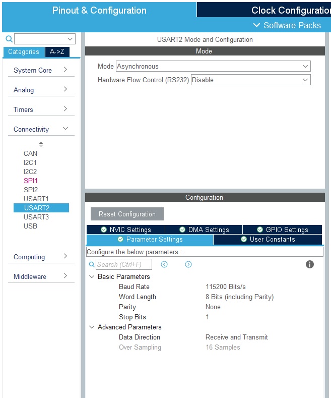
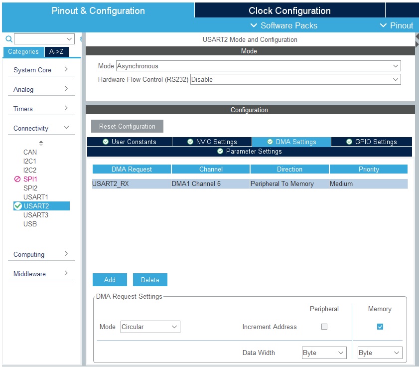
Configure your platform to use DMA with USART2:
1) Open up "Pinout & Configuration" tab (accessible by opening your project's .ioc file)
2) Open up Connectivity -> USART2
3) Select the "DMA Settings" tab, and click "Add" at the bottom of the dialog.
4) Select "USART2_RX" from the pull-down menu
5) Select "Circular" for Mode, Byte Data width, and "Memory" for Increment Address
Using the JTAG (SWD) Debugger
This assumes you have a project that builds and maybe runs to some degree, but something is broken...
1) Instead of the "Run" button, click on the "Run->Debug As..."
2) Using the JTAD (SWD) debugger, the application will launch, and stop at a breakpoint set at HAL_Init(),
   allowing you to begin debugging from there.
3) Set a breakpoint where you want to begin debugging, example - at the MX_GPIO_Init() call.
4) Click the "Resume" button, allowing the processor to run until it hits the breakpoint
5) You can "Step Into" (F5), or "Step Over" (F6) lines of code.
   You can also step out of a function using "Step Return" (F7)

STM32Cube Monitor:
https://www.st.com/en/development-tools/stm32cubemonitor.html
Where is everything?
Once an STM32 processor or development board is selected, STM32CubeIDE downloads and installs
a firmware package for the device selected.
I found the install location for the “F1” firmware here:
C:\Users\JimMerkle\STM32Cube\Repository\STM32Cube_FW_F1_V1.8.4
Within this folder are header files, HAL source code, middleware, driver code,
example code, and documentation for the firmware package.

Each project includes a copy of the header files needed for a build.
(Just drill down inside the project's Driver folder.)  Example:
C:\Users\JimMerkle\Documents\STM32_Projects\NUCLEO-F103RB_Blinky\Drivers\STM32F1xx_HAL_Driver\Inc\stm32f1xx_hal_gpio.h
Additional Resources:
Shawn Hymel - How to use printf() on stm32
Digikey Forum: Easily Use Printf On STM32
NUCLEO-F103RB Documentation - Mbed

