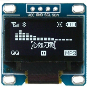
SSD1306 128x64 I2C OLED Display
Jump to navigation
Jump to search
Hardware

These displays use the SSD1306 controller: https://cdn-shop.adafruit.com/datasheets/SSD1306.pdf
D0     SCL - I2C Clock signal
D1     SDA - I2C Data signal
RES#   This pin is reset signal input. When the pin is pulled LOW, initialization of the chip is executed.
       Keep this pin HIGH (i.e. connect to VDD) during normal operation.
D/C#   In I2C mode, this pin acts as SA0 for slave address selection.
       LOW:  I2C Address 0x3C
       HIGH: I2C Address 0x3D
Notes:
The SSD1306 is capable of using a 400KHz I2C clock

If you're not sure if your device's I2C address 0x3C or 0x3D, you can run the Arduio "i2c_scanner" example program
File->Examples->Wire->i2c_scanner
This should identify your connected SSD1306 chip as either 0x3C or 0x3D.
Connections
Display  Arduino
  GND    Ground
  VCC     +5V
  SCL     A5
  SDA     A4
We can see the Arduino is using a 400KHz clock
The I2C address is 0x3C
Capture showing the time it takes to send a complete frame ~37ms
Software
For Arduino, the Adafruit SSD1306 library, version 2.4.2, works very well.
For testing, I used libraries\Adafruit_SSD1306\examples\ssd1306_128x64_i2c.ino example.
Although the example calls out pin 4 as OLED_RESET, this isn't required.
The example uses I2C address, 0x3D for the display, with the comment, "Address 0x3D for 128x64".
Since the I2C address is dependent on the D/C# signal connection on the module, this is module dependant.
My module uses I2C address 0x3C.
Source Code Modification
This was required for my display to work
 // SSD1306_SWITCHCAPVCC = generate display voltage from 3.3V internally
 if(!display.begin(SSD1306_SWITCHCAPVCC, 0x3C)) { // Address 0x3D for 128x64 (This is defined by the module)
   Serial.println(F("SSD1306 allocation failed"));
   for(;;); // Don't proceed, loop forever
 }
Additional Resources
https://www.robot-electronics.co.uk/i2c-tutorial

