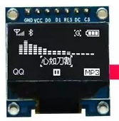
SSD1306 128x64 SPI OLED Display
Hardware


These displays use the SSD1306 controller: https://cdn-shop.adafruit.com/datasheets/SSD1306.pdf
The following is from the SSD1306.pfd document:
8.1.3 MCU Serial Interface (4-wire SPI)
The 4-wire serial interface consists of serial clock: SCLK, serial data: SDIN (MOSI), D/C#, CS#.
In 4-wire SPI mode, D0 is used for SCLK signal, D1 is used for MOSI. For the unused data pins, D2 should be left open.
The pins from D3 to D7, E and R/W# (WR#)# can be connected to an external ground.

Table 8-4 : Control pins of 4-wire Serial interface
Function        E(RD#)	  R/W#(WR#)   CS#    D/C#   D0
Write command  Tie LOW   Tie LOW      L      L      ↑
Write data     Tie LOW	  Tie LOW      L      H      ↑
Note
(1) H stands for HIGH signal
(2) L stands for LOW signal

RES#   This pin is reset signal input. When the pin is pulled LOW, initialization of the chip is executed.
       Keep this pin HIGH (i.e. connect to VDD) during normal operation.
D/C#   This is Data/Command control pin. When LOW, it indicates a command to be sent to the command register.
       When HIGH, it indicates data.
       In I2C mode, this pin acts as SA0 for slave address selection.
       When 3-wire serial interface is selected, this pin must be tied low (connected to VSS).
CS#  This pin is the chip select input. (active LOW).

NOTE: This device uses SPI mode 0.
Note the diagram on the back of the SSD1306 module.  It documents resistor population for different
processor interfaces.  This one came configured perfectly for "4SPI" connection.
For this exercise, I used the SPI (4 wire) Hardware interface, with reset (RES#) added. (I don't believe MISO is used.)
According to the datasheet, the maximum SPI clock frequency is 10MHz.
Connections
Board	       MOSI    MISO	SCK	RES#	CS#	D/C#
Arduino UNO	11	12	13	8	7	6
Arduino Uno - Hardware SPI - Screen Captures

Before each frame, the Arduino sends six command bytes before sending the frame data

Capture showing the time it takes to send a complete frame - 2.79ms

With a single byte SPI buffer (no FIFO), and not using DMA, it takes time to load each byte for transfer.
If DMA were available and implemented, the frame time could be reduced considerably.
The sending of a single byte takes 1.0us using an 8MHz SPI clock.
We see the Arduino is sending bytes about every 2.69us.

This capture shows we are using an 8MHz clock. The maximum clock for this part is 10MHz, so this is about as fast as the Arduino UNO can send SPI data.
Software
For Arduino, the Adafruit SSD1306 library, version 2.4.2, works very well.
For testing, I used libraries\Adafruit_SSD1306\examples\ssd1306_128x64_spi.ino example.
For hardware SPI, need to follow the directions at the top of the file, commenting out the software SPI defines
and constructor (default case), and uncomment the hardware SPI defines and constructor.
It should look something like the following:
/*
// Declaration for SSD1306 display connected using software SPI (default case):
#define OLED_MOSI   9
#define OLED_CLK   10
#define OLED_DC    11
#define OLED_CS    12
#define OLED_RESET 13
Adafruit_SSD1306 display(SCREEN_WIDTH, SCREEN_HEIGHT,
  OLED_MOSI, OLED_CLK, OLED_DC, OLED_RESET, OLED_CS);
*/

/* Comment out above, uncomment this block to use hardware SPI */
#define OLED_DC     6
#define OLED_CS     7
#define OLED_RESET  8
Adafruit_SSD1306 display(SCREEN_WIDTH, SCREEN_HEIGHT,
  &SPI, OLED_DC, OLED_RESET, OLED_CS);
Additional Resources
https://learn.adafruit.com/monochrome-oled-breakouts/wiring-128x32-spi-oled-display