MicroPython on STM32F407G-DISC1
MicroPython, https://micropython.org/, a subset of the popular Python 3 programming language, is available to run on many development boards, including a large selection from STMicro.
The original development platform for MicroPython is the Pyboard, using an STM32F405RG microcontroller with 168 MHz Cortex M4 CPU, hardware floating point, 1024KiB flash ROM, and 192KiB RAM.
https://store.micropython.org/product/PYBv1.1H
Due to its feature set, lower price, and additional hardware, I chose the {{#if:|{{#ifexpr:({{#time:U|{{{3}}}}} - {{#time:U|now}}) > 0|STM32F407G-DISC1 Discovery Board|STM32F407G-DISC1 Discovery Board}}|STM32F407G-DISC1 Discovery Board}},
https://www.st.com/en/evaluation-tools/stm32f4discovery.html, for $19.50.
Program a MicroPython Image onto the STM32F407G-DISC1 Discovery Board
A MicroPython image for the board: https://micropython.org/download/stm32/ - Scroll down to Firmware For STM32F4DISC board
I downloaded the {{#if:|{{#ifexpr:({{#time:U|{{{3}}}}} - {{#time:U|now}}) > 0|STM32F4DISC-20210418-v1.15.dfu|STM32F4DISC-20210418-v1.15.dfu}}|STM32F4DISC-20210418-v1.15.dfu}} image for my board.
Although many of the associated web pages use the DFU loader to program the MicroPython image into the microcontroller,
I chose to use the on-board JTAG adapter, making this a very easy three step process:
* Download an appropriate image for the development board
* Convert the .DFU image to .HEX using the DFU File Manager (Part of the DfuSe package).
  https://www.st.com/en/development-tools/stsw-stm32080.html
* Using STM32CubeProgrammer, write the .HEX file to the STM32F407G target processor.
  https://www.st.com/en/development-tools/stm32cubeprog.html
Note: If you have difficulty connecting to the target processor with the STM32CubeProgrammer, I have two suggestions:
If the first one doesn't work, try the second...
1) On the right side of the dialog box, change "Reset mode" to "Hardware reset" <- This should always work
2) Press and hold the reset button on the target, click the "Connect" button and then release the reset button.
   (This one often works where the ST-Link JTAG adapter doesn't have control of the target's reset signal.)
MicroPython with the STM32F407G-DISC1 Discovery Board creates a USB Virtual COM Port as well as a USB Drive, PYBFLASH, when connected to a Host computer.
Files may be added (or modified) within the PYBFLASH drive.
Use TeraTerm, Putty, or other serial terminal program to connect to the USB Virtual COM Port
What Can I Do with MicroPython and the STM32F407G-DISC1 Discovery Board?
Let's begin with some simple exercises...
Blue LED ON / Blue LED OFF
See https://docs.micropython.org/en/latest/library/pyb.LED.html
# Turn Blue LED on and off (4 is the blue LED)
blue=pyb.LED(4)
blue.on()
blue.off()
The above exercise, entered via the REPL interpreter, will create an LED object, called "blue"
The LED member functions on(), and off() perform as expected.
Blink Four LEDs (blinky1.py)
# blinky1.py
# LED color vs number: 1: red, 2: green, 3: orange, 4: blue
import pyb
msdelay = 300 # ms delay
# Create list of LED objects in the order you wish to have them blink
leds = [pyb.LED(3),pyb.LED(1),pyb.LED(4),pyb.LED(2)]
while True:
    for led in leds:
        led.on()
        pyb.delay(msdelay)
        led.off()
The above text may be copied - paste into a file, blinky1.py, on the PYBFLASH drive
At the REPL prompt, enter:
>>> import blinky1
That will cause the file, blinky1.py, to be loaded and executed
- Use control-C  ^C  to break from loop and return to REPL interpreter
Switch with Orange LED (switch1.py)
See: https://docs.micropython.org/en/latest/library/pyb.Switch.html
# switch1.py
# When switch pressed, turn on orange LED, when released, turn off orange LED
orange=pyb.LED(3)
sw=pyb.Switch()
while True:
    if sw():
        orange.on()
    else:
        orange.off()
# Blink External LED using GPIO (gpioled.py)
See: https://docs.micropython.org/en/latest/library/machine.Pin.html
#gpioled.py
import pyb
myled=pyb.Pin('PC7',mode=pyb.Pin.OUT)
while True:
    myled.value(True)
    pyb.delay(300)
    myled.value(False)
    pyb.delay(300)
value() may be used to read or write the value of a Pin
Instead of member function value(), you can use high(), low(), on(), off()
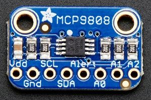
Read Temperature using MCP9808 with I2C (mcp9808.py)
See: https://docs.micropython.org/en/latest/library/pyb.I2C.html

#mcp9808.py
import machine
import pyb
#It appears I2C has been deprecated, replaced with SoftI2C
#SoftI2C requires Pins for scl and sda
mcp9808=0x18
i2c=machine.SoftI2C(scl=pyb.Pin('PD2'),sda=pyb.Pin('PD3'),freq=100000)
def readtemp():
    raw = i2c.readfrom_mem(mcp9808,5,2) # read two bytes into buffer
    u = (raw[0] & 0xf) << 4
    l = raw[1] >> 4
    if raw[0] & 0x10 == 0x10: # check sign bit
        temp = (u + l) - 256
        frac = -((raw[1] & 0x0f) * 100 >> 4)
    else:
        temp = u + l
        frac = (raw[1] & 0x0f) * 100 >> 4
    #print('temp:',temp,'  frac:',frac)
    print('{}.{:02}C'.format(temp,frac))
Reading the temperature:
>>> import mcp9808a
>>> mcp9808a.readtemp()
24.87C
Draw text and graphics with SSD1306 I2C OLED Display
Although my buddy, Pete, and I, were able to interface this display with the board, we later found the following
  web page that documents this exercise VERY WELL (Excellent work Miguel Grinberg!):
https://blog.miguelgrinberg.com/post/micropython-and-the-internet-of-things-part-vi-working-with-a-screen
This exercise turned out very well, but the 8x8 font is too small.
To solve the font problem, the same web page documents a solution involving the following
  MicroPython scripts, freesans20.py and writer.py.  Give this solution a try...
freesans20.py: https://raw.githubusercontent.com/miguelgrinberg/micropython-iot-tutorial/master/chapter6/freesans20.py
writer.py:     https://raw.githubusercontent.com/miguelgrinberg/micropython-iot-tutorial/master/chapter6/writer.py
Using the CAN interface
See: https://docs.micropython.org/en/latest/library/pyb.CAN.html
My biggest initial problem working with the CAN interface on this board was to determine what pins the
board is using for TX and RX with an external transceiver.
I downloaded the source code, https://github.com/micropython/micropython, to determine the Micropython image
is using pins PB8: CAN1_RX, and PB9: CAN1_TX.  Further studying and testing showed that
CAN.LOOPBACK mode as CAN.NORMAL mode BOTH produced CAN Bus signal output on pin PB9.
Begin with mode: CAN.LOOPBACK:
#cantest.py
from pyb import CAN
can = CAN(1, mode=CAN.LOOPBACK,baudrate=50000) # Create CAN object, 50K baudrate
can.send('123',0x123) # Send a message with 3 data bytes 'o','n','e', using ID 0x123
#Resulting message measured 1.18ms from initial falling edge to last rising edge, 20us/bit (59 bits)
can = CAN(1, mode=CAN.LOOPBACK,baudrate=100000) # Create CAN object with 100K baudrate
can.send('123',0x123)
#Resulting message measures 588us
can = CAN(1, mode=CAN.LOOPBACK,baudrate=10000) # Create CAN object, 10K baudrate
can.send('123',0x123)
It was found that the CAN constructor didn't reliably change the baud rate, but that the init() function did.
Reference / Additional Information
https://micropython.org